Mechanical Drawing Symbols

Electrical Symbols, Electrical Diagram Symbols

The vector stencils library "Bearings" contains 59 symbols of ball bearings, roller bearings, shafts, springs, gears, hooks, spindles, and keys.
Use it to design engineering drawings of machine tools and mechanical devices.
"A bearing is a machine element that constrains relative motion and reduce friction between moving parts to only the desired motion. The design of the bearing may, for example, provide for free linear movement of the moving part or for free rotation around a fixed axis; or, it may prevent a motion by controlling the vectors of normal forces that bear on the moving parts. Many bearings also facilitate the desired motion as much as possible, such as by minimizing friction. Bearings are classified broadly according to the type of operation, the motions allowed, or to the directions of the loads (forces) applied to the parts." [Bearing (mechanical). Wikipedia]
The shapes example "Design elements - Bearings" was created using the ConceptDraw PRO diagramming and vector drawing software extended with the Mechanical Engineering solution from the Engineering area of ConceptDraw Solution Park.
Bearing symbols

The vector stencils library "Valve assembly" contains 141 symbols of pressure and flow regulators, flow direction indicators, controls, and symbols to design flow paths of control valves.
Use these valve assembly shapes to design the engineering drawings of hydraulic and pneumatic valve assemblies in fluid power systems.
"Control valves are valves used to control conditions such as flow, pressure, temperature, and liquid level by fully or partially opening or closing in response to signals received from controllers that compare a "setpoint" to a "process variable" whose value is provided by sensors that monitor changes in such conditions.
The opening or closing of control valves is usually done automatically by electrical, hydraulic or pneumatic actuators. Positioners are used to control the opening or closing of the actuator based on electric, or pneumatic signals.
A control valve consists of three main parts in which each part exist in several types and designs: Valve's actuator, Valve's positioner, Valve's body.
" [Control valves. Wikipedia]
The shapes example "" was created using the ConceptDraw PRO diagramming and vector drawing software extended with the Mechanical Engineering solution from the Engineering area of ConceptDraw Solution Park.
Valve assembly symbols

Process Flow Diagram Symbols

Technical Drawing Software

Mechanical Design Software

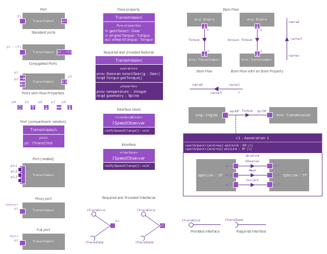
The vector stencils library "Ports and Flows" contains 26 SysML symbols.
Use it to design your SysML diagrams using ConceptDraw PRO diagramming and vector drawing software.
"The main motivation for specifying ports and flows is to enable design of modular, reusable blocks with clearly defined
ways of connecting and interacting with their context of use. This clause extends UML ports to support nested ports, and
extends blocks to support flow properties, and required and provided features, including blocks that type ports. Ports can be typed by blocks that support operations, receptions, and properties as in UML. SysML defines a specialized form of Block (InterfaceBlock) that can be used to support nested ports. SysML identifies two kinds of ports, one that exposes
features of the owning block or its internal parts (proxy ports), and another that supports its own features (full ports). Default compatibility rules are defined for connecting blocks used in composite structure, including parts and ports, with association blocks available to define more specific ways of doing this. These additional capabilities in SysML enable modelers to specify a wide variety of interconnectable components, which can be implemented through many engineering and social techniques, such as software, electrical or mechanical components, and human organizations. This clause also extends UML information flows for specifying item flows across connectors and associations." [www.omg.org/ spec/ SysML/ 1.3/ PDF]
The SysML shapes example "Design elements - Ports and Flows" is included in the SysML solution from the Software Development area of ConceptDraw Solution Park.
SysML ports and flows symbols
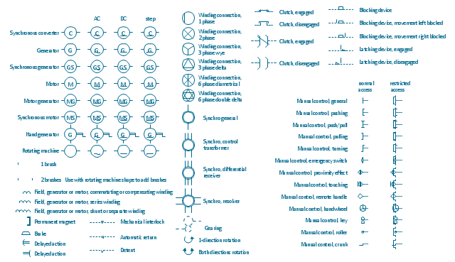
The vector stencils lybrary "Rotating equipment" contains 55 symbols of rotating equipment: converters, generators, motors, rotating machines, and their parts and labels.
Use to design systems containing rotating electrical equipment (i.e., motors), armatures, brushes, and related mechanical devices ( brakes, gearing, clutches, interlocks).
"The academic study of electric machines is the universal study of electric motors and electric generators. By the classic definition, electric machine is synonymous with electric motor or electric generator, all of which are electromechanical energy converters: converting electricity to mechanical power (i.e., electric motor) or mechanical power to electricity (i.e., electric generator). The movement involved in the mechanical power can be rotating or linear.
Although transformers do not contain any moving parts they are also included in the family of electric machines because they utilise electromagnetic phenomena.
Electric machines (i.e., electric motors) consume approximately 60% of all electricity produced. Electric machines (i.e., electric generators) produce virtually all electricity consumed. Electric machines have become so ubiquitous that they are virtually overlooked as an integral component of the entire electricity infrastructure. Developing ever more efficient electric machine technology and influencing their use are crucial to any global conservation, green energy, or alternative energy strategy." [Electric machine. Wikipedia]
The shapes example "Design elements - Rotating equipment" was drawn using the ConceptDraw PRO diagramming and vector drawing software extended with the Electrical Engineering solution from the Engineering area of ConceptDraw Solution Park.
Rotating equipment symbols
The vector stencils library "Pumps" contains 82 symbols of pumps, compressors, fans, turbines, and power generators.
Use these icons to design pumping systems, air and fluid compression systems, and industrial process diagrams.
"A pump is a device that moves fluids (liquids or gases), or sometimes slurries, by mechanical action. Pumps can be classified into three major groups according to the method they use to move the fluid: direct lift, displacement, and gravity pumps.
Pumps operate by some mechanism (typically reciprocating or rotary), and consume energy to perform mechanical work by moving the fluid. Pumps operate via many energy sources, including manual operation, electricity, engines, or wind power, come in many sizes, from microscopic for use in medical applications to large industrial pumps.
Mechanical pumps serve in a wide range of applications such as pumping water from wells, aquarium filtering, pond filtering and aeration, in the car industry for water-cooling and fuel injection, in the energy industry for pumping oil and natural gas or for operating cooling towers. In the medical industry, pumps are used for biochemical processes in developing and manufacturing medicine, and as artificial replacements for body parts, in particular the artificial heart and penile prosthesis.
In biology, many different types of chemical and bio-mechanical pumps have evolved, and biomimicry is sometimes used in developing new types of mechanical pumps." [Pump. Wikipedia]
The example "Design elements - Pumps" was created using the ConceptDraw PRO diagramming and vector drawing software extended with the Chemical and Process Engineering solution from the Engineering area of ConceptDraw Solution Park.
Pump symbols

The vector stencils library "Dimensioning and tolerancing" contains 45 symbols of geometric dimensions and mechanical tolerances, geometric symbols, callouts, and text boxes and inserts.
Use these geometric dimensioning and tolerancing (GD&T) shapes to create annotated mechanical drawings.
"Geometric dimensioning and tolerancing (GD&T) is a system for defining and communicating engineering tolerances. It uses a symbolic language on engineering drawings and computer-generated three-dimensional solid models that explicitly describes nominal geometry and its allowable variation. It tells the manufacturing staff and machines what degree of accuracy and precision is needed on each controlled feature of the part. GD&T is used to define the nominal (theoretically perfect) geometry of parts and assemblies, to define the allowable variation in form and possible size of individual features, and to define the allowable variation between features." [Geometric dimensioning and tolerancing. Wikipedia]
The shapes example "Design elements - Dimensioning and tolerancing" was created using the ConceptDraw PRO diagramming and vector drawing software extended with the Mechanical Engineering solution from the ConceptDraw Solution Park.
Dimensioning and tolerancing symbols

Mathematics Symbols

The vector stencils library "Fluid power valves" contains 93 symbols of pre-made hydraulic and pneumatic valves, including directional control valves, flow control valves, pressure control valves, and electrohydraulic and electropneumatic valves.
"Control valves are valves used to control conditions such as flow, pressure, temperature, and liquid level by fully or partially opening or closing in response to signals received from controllers that compare a "setpoint" to a "process variable" whose value is provided by sensors that monitor changes in such conditions.
The opening or closing of control valves is usually done automatically by electrical, hydraulic or pneumatic actuators. Positioners are used to control the opening or closing of the actuator based on electric, or pneumatic signals.
A control valve consists of three main parts in which each part exist in several types and designs: Valve's actuator, Valve's positioner, Valve's body.
" [Control valves. Wikipedia]
The shapes example "Design elements - Fluid power valves" was created using the ConceptDraw PRO diagramming and vector drawing software extended with the Mechanical Engineering solution from the Engineering area of ConceptDraw Solution Park.
Fluid power valve symbols

Electrical Drawing Software and Electrical Symbols

Interior Design. Machines and Equipment — Design Elements

Electrical and Telecom Plan Software

The vector stencils libraries "Pipes 1" and "Pipes 2" contain 28 and 48 pipe, tubing and fitting symbols, respectively.
"Pipe is hollow cylinder used to conduct or transfer fluids (liquids and gases) from one place to other place. The main difference between pipe and tube is the critical dimension used to describe the pipe size or the tube size. For pipe, internal diameter (ID) roughly corresponds to the nominal pipe size for standard wall thickness. For tube, the outer diameter (OD) closely corresponds to the tube size. In current European standards pipes and tubes are nowadays described as outside diameter by wall thickness. The three standard types of pipe ends used in the piping industriesare; Plain Ends (PE), Threaded Ends (TE) and Beveled Ends (BE). In the past, many types of material have been used in conveying water from one point to another. Masonry and wood were probably the first materials used. Plastics are the newest, and are now being used quite extensively." [Piping. Wikipedia]
Use the design elements libraries "Pipes 1" and "Pipes 2" for drawing plumbing and piping building plans, schematic diagrams, blueprints, or technical drawings of waste water disposal systems, hot and cold water supply systems using the ConceptDraw PRO diagramming and vector drawing software.
The shapes libraries "Pipes 1" and "Pipes 2" are contained in the Plumbing and Piping Plans solution from the Building Plans area of ConceptDraw Solution Park.
Piping symbols
.png--diagram-flowchart-example.png)
Building Drawing. Design Element — Plumbing

How To Create Emergency Plans and Fire Evacuation

- Geometric Symbols Of Machine Design
- Mechanical Drawing Symbols | Design elements - Dimensioning ...
- Symbol Used To Design Machine Element
- Mechanical Drawing Symbols | Design elements - Bearings ...
- Symbolic Representation Of Machine Design
- Mechanical Components Symbols
- Mechanical Drawing Symbols | Design elements - Bearings | Create ...
- Mechanical Drawing Symbols | Home Electrical Plan | Mechanical ...
- Design elements - Pumps | Injection Pump Symbol
- Design elements - Machines and equipment | Design elements ...
- Mechanical Design Symbols Representation
- Symbols Used In Mechanical Project Drawing
- Design elements - Machines and equipment | Design elements ...
- Design elements - Ports and Flows | Design elements - UML ...
- Mechanical Engineering | Design elements - Valve assembly ...
- Symbols Of Mechanical Components
- Mechanical Drawing Symbols | Mechanical Engineering ...
- Mechanical Drawing Symbols | Interior Design . Machines and ...
- Design elements - Dimensioning and tolerancing | Network ...