- Electric and Telecom Plans Free
- Fire and Emergency Plans Free
- Floor Plans Free
- Plant Layout Plans Free
- School and Training Plans Free
- Seating Plans Free
- Security and Access Plans Free
- Site Plans Free
- Sport Field Plans Free
- Business Process Diagrams Free
- Business Process Mapping Free
- Classic Business Process Modeling Free
- Cross-Functional Flowcharts Free
- Event-driven Process Chain Diagrams Free
- IDEF Business Process Diagrams Free
- Logistics Flow Charts Free
- Workflow Diagrams Free
- ConceptDraw Dashboard for Facebook Free
- Mind Map Exchange Free
- MindTweet Free
- Note Exchange Free
- Project Exchange Free
- Social Media Response Free
- Active Directory Diagrams Free
- AWS Architecture Diagrams Free
- Azure Architecture Free
- Cisco Network Diagrams Free
- Cisco Networking Free
- Cloud Computing Diagrams Free
- Computer Network Diagrams Free
- Google Cloud Platform Free
- Interactive Voice Response Diagrams Free
- Network Layout Floor Plans Free
- Network Security Diagrams Free
- Rack Diagrams Free
- Telecommunication Network Diagrams Free
- Vehicular Networking Free
- Wireless Networks Free
- Comparison Dashboard Free
- Composition Dashboard Free
- Correlation Dashboard Free
- Frequency Distribution Dashboard Free
- Meter Dashboard Free
- Spatial Dashboard Free
- Status Dashboard Free
- Time Series Dashboard Free
- Basic Circle-Spoke Diagrams Free
- Basic Circular Arrows Diagrams Free
- Basic Venn Diagrams Free
- Block Diagrams Free
- Concept Maps Free
- Family Tree Free
- Flowcharts Free
- Basic Area Charts Free
- Basic Bar Graphs Free
- Basic Divided Bar Diagrams Free
- Basic Histograms Free
- Basic Line Graphs Free
- Basic Picture Graphs Free
- Basic Pie Charts Free
- Basic Scatter Diagrams Free
- Aerospace and Transport Free
- Artwork Free
- Audio, Video, Media Free
- Business and Finance Free
- Computers and Communications Free
- Holiday Free
- Manufacturing and Maintenance Free
- Nature Free
- People Free
- Presentation Clipart Free
- Safety and Security Free
- Analog Electronics Free
- Audio and Video Connectors Free
- Basic Circuit Diagrams Free
- Chemical and Process Engineering Free
- Digital Electronics Free
- Electrical Engineering Free
- Electron Tube Circuits Free
- Electronic Block Diagrams Free
- Fault Tree Analysis Diagrams Free
- GHS Hazard Pictograms Free
- Home Automation and Wiring Free
- Mechanical Engineering Free
- One-line Diagrams Free
- Power Сircuits Free
- Specification and Description Language (SDL) Free
- Telecom and AV Circuits Free
- Transport Hazard Pictograms Free
- Data-driven Infographics Free
- Pictorial Infographics Free
- Spatial Infographics Free
- Typography Infographics Free
- Calendars Free
- Decision Making Free
- Enterprise Architecture Diagrams Free
- Fishbone Diagrams Free
- Organizational Charts Free
- Plan-Do-Check-Act (PDCA) Free
- Seven Management and Planning Tools Free
- SWOT and TOWS Matrix Diagrams Free
- Timeline Diagrams Free
- Australia Map Free
- Continent Maps Free
- Directional Maps Free
- Germany Map Free
- Metro Map Free
- UK Map Free
- USA Maps Free
- Customer Journey Mapping Free
- Marketing Diagrams Free
- Matrices Free
- Pyramid Diagrams Free
- Sales Dashboard Free
- Sales Flowcharts Free
- Target and Circular Diagrams Free
- Cash Flow Reports Free
- Current Activities Reports Free
- Custom Excel Report Free
- Knowledge Reports Free
- MINDMAP Reports Free
- Overview Reports Free
- PM Agile Free
- PM Dashboards Free
- PM Docs Free
- PM Easy Free
- PM Meetings Free
- PM Planning Free
- PM Presentations Free
- PM Response Free
- Resource Usage Reports Free
- Visual Reports Free
- House of Quality Free
- Quality Mind Map Free
- Total Quality Management TQM Diagrams Free
- Value Stream Mapping Free
- Astronomy Free
- Biology Free
- Chemistry Free
- Language Learning Free
- Mathematics Free
- Physics Free
- Piano Sheet Music Free
- Android User Interface Free
- Class Hierarchy Tree Free
- Data Flow Diagrams (DFD) Free
- DOM Tree Free
- Entity-Relationship Diagram (ERD) Free
- EXPRESS-G data Modeling Diagram Free
- IDEF0 Diagrams Free
- iPhone User Interface Free
- Jackson Structured Programming (JSP) Diagrams Free
- macOS User Interface Free
- Object-Role Modeling (ORM) Diagrams Free
- Rapid UML Free
- SYSML Free
- Website Wireframe Free
- Windows 10 User Interface Free
Class Hierarchy Tree
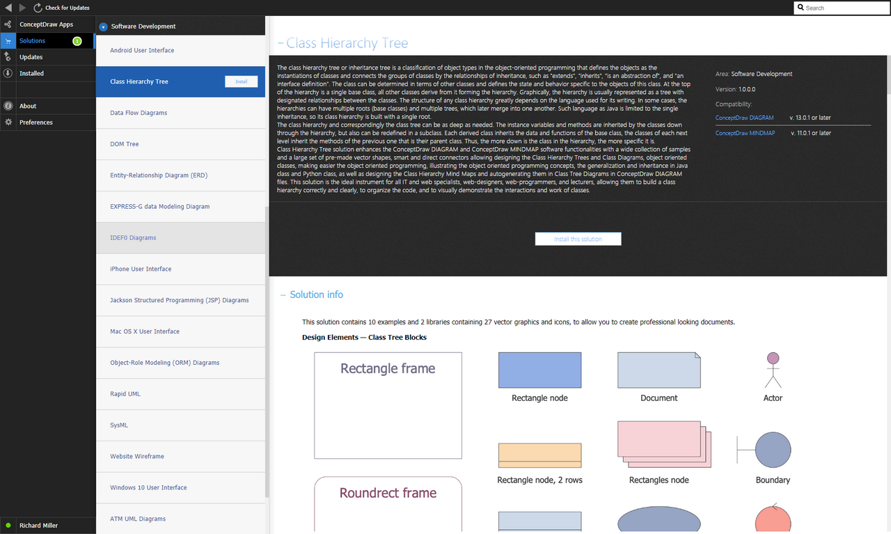
The Class Hierarchy Tree or Inheritance Tree is a classification of object types in object-oriented programming, which defines objects as instances of classes and connects class groups with inheritance relationships, such as “extends”, “inherits”, “it is an abstraction” and “interface definition”. The class can be determined in terms of other classes and defines the state and behavior specific to the objects of this class. At the top of the hierarchy is a single base class, all other classes derive from it forming the hierarchy. Graphically, the hierarchy is usually presented as a tree with designated relationships between the classes. The structure of any class hierarchy greatly depends on the language used for its writing. In some cases, the hierarchies can have multiple roots (base classes) and multiple trees, which subsequently merge into one another. Such language as Java is limited to the single inheritance, so its class hierarchy is built with a single root.
The class hierarchy and correspondingly the class tree can be as deep as necessary. The instance variables and methods are inherited by the classes down through the hierarchy, but can also be redefined in a subclass. Each derived class inherits the data and functions of the base class, the classes of each next level inherit methods of the previous one that is their parent class. Thus, the lower the class in the hierarchy, the more specific it is.
The Class Hierarchy Tree solution enhances the functionality of the ConceptDraw DIAGRAM and ConceptDraw MINDMAP software with a wide range of samples and a large set of ready-made vector shapes, smart and direct connectors allowing to create the Class Hierarchy Trees and Class Diagrams, object-oriented classes, making object-oriented programming easier illustrating the concepts of object-oriented programming, generalization and inheritance in the Java and Python classes, as well as the design of Class Hierarchy Mind Maps and their automatic creation in class tree diagrams in ConceptDraw DIAGRAM files. This solution is an ideal instrument for all IT and web specialists, web-designers, web-programmers, and lecturers, allowing them to correctly and clearly build class hierarchies, organize code and clearly demonstrate how classes interact and work.
-
Install this solution Free -
What I need to get started -
Solution Requirements - This solution requires the following products to be installed:
ConceptDraw DIAGRAM v18 ConceptDraw MINDMAP v16 - This solution requires the following products to be installed:
-
Compatibility - Sonoma (14), Sonoma (15)
MS Windows 10, 11 - Sonoma (14), Sonoma (15)
-
Support for this Solution -
Helpdesk
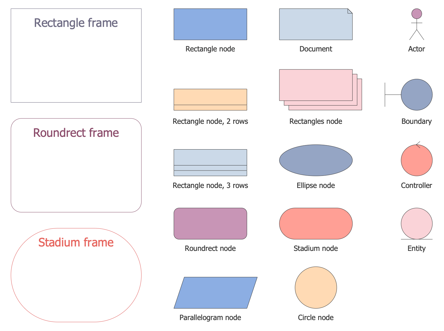
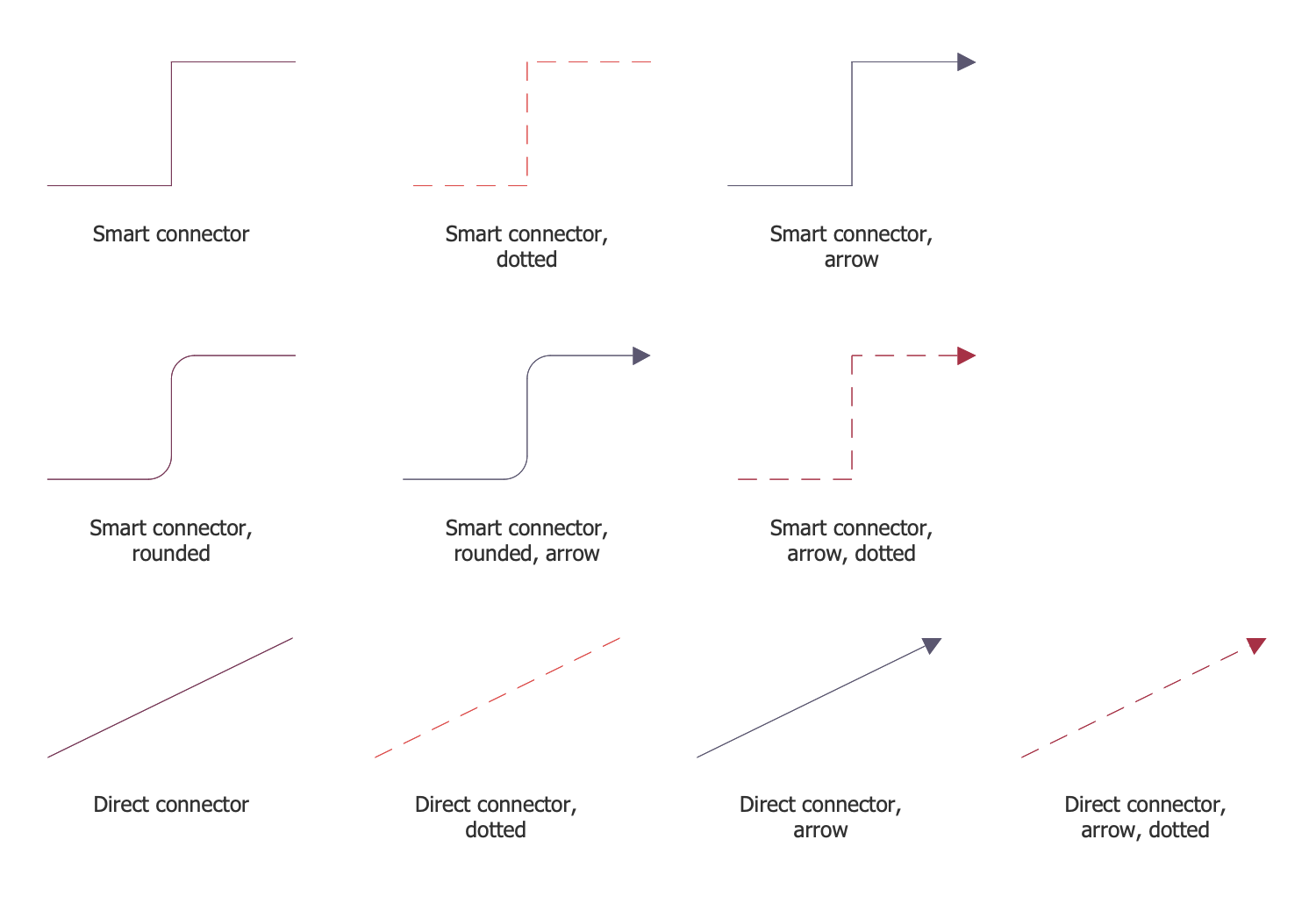
This solution contains 10 examples and 2 libraries containing 27 vector graphics and icons, which allow you to create professional-looking documents.
Design Elements — Class Tree Blocks
Design Elements — Class Tree Connectors
Examples
There are a few samples that you see on this page which were created in the ConceptDraw DIAGRAM application by using the Class Hierarchy Tree solution. Some of the solution's capabilities, as well as the professional results which you can achieve are demonstrated here on this page.
All source documents are vector graphic documents which are always available for modifying, reviewing and/or converting to many different formats, such as MS PowerPoint, PDF file, MS Visio, and many other graphic files from the ConceptDraw Solution Park or ConceptDraw STORE. The Class Hierarchy Tree solution is available to all ConceptDraw DIAGRAM users for installation and used while working in the ConceptDraw DIAGRAM diagramming and drawing software.Example 1: ECB Class Diagram
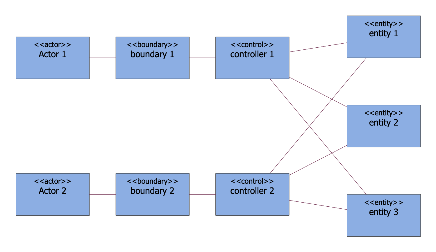
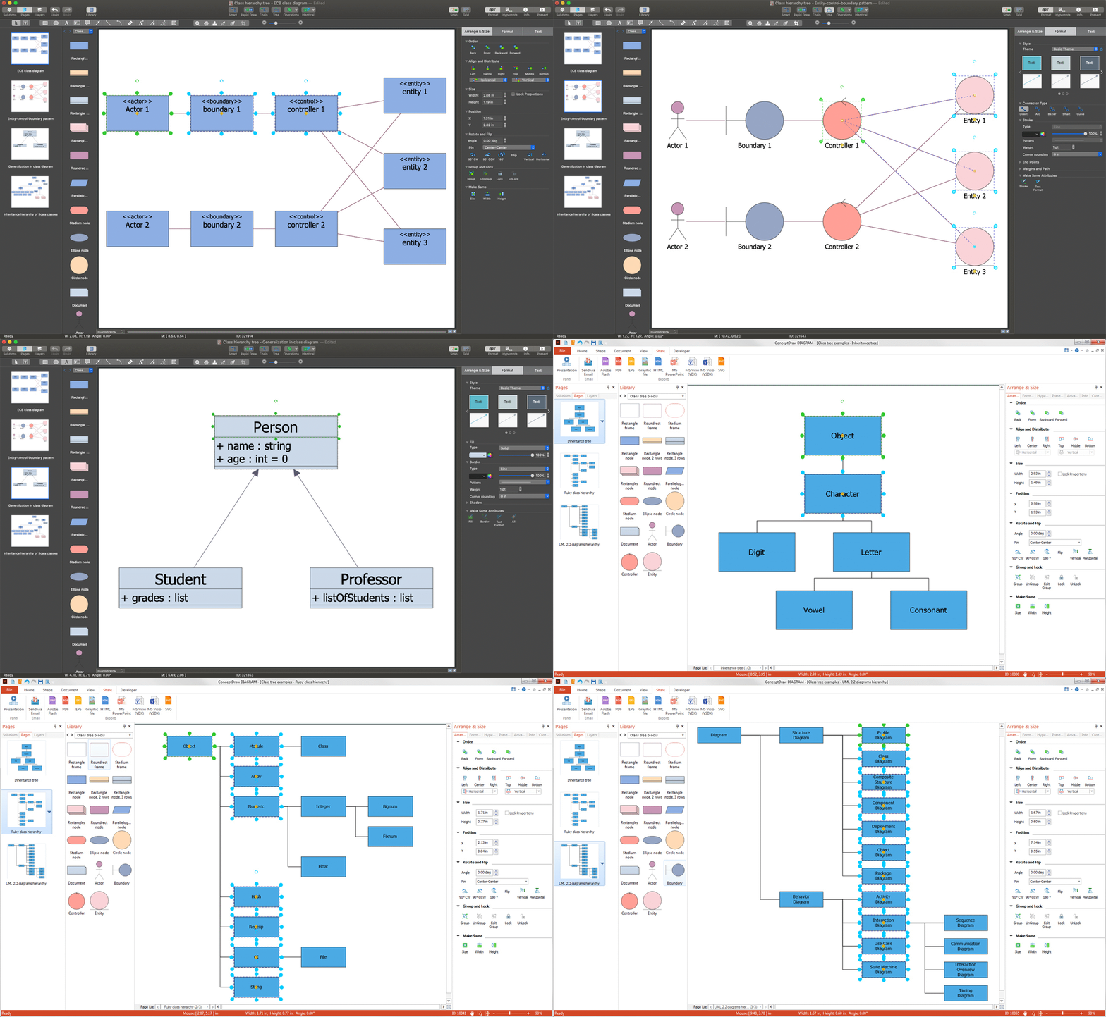
This diagram was created in ConceptDraw DIAGRAM using the combination of libraries from the Class Hierarchy Tree solution. An experienced user spent 5 minutes creating this sample.
This sample diagram illustrates the ECB (Entity-Control-Boundary) Class Diagram. The analysis object model instantiates the ECB Pattern that is a simplification of the Model-View-Controller (MVC) Pattern. The ECB divides the system into three types of classes: entities, controls, and boundaries, which are also official stereotypes of UML classes. The entities are objects that represent system data, such as Product, Customer, Transaction, Cart, etc. The boundaries are objects that interact with the system actors, such as ServerProxy, UserInterface, DataBaseGateway, etc. and, finally, control elements are objects that act as intermediaries between boundaries and entities and organize the execution of commands coming from interaction entities and boundary objects. Typically, the controls correspond to use cases in the design model. UML uses some special icons to represent them, but there are no special icons on this diagram, and they are all presented as boxes.
Example 2: Entity-Control-Boundary Pattern
This diagram was created in ConceptDraw DIAGRAM using the combination of libraries from the Class Hierarchy Tree solution. An experienced user spent 5 minutes creating this sample.
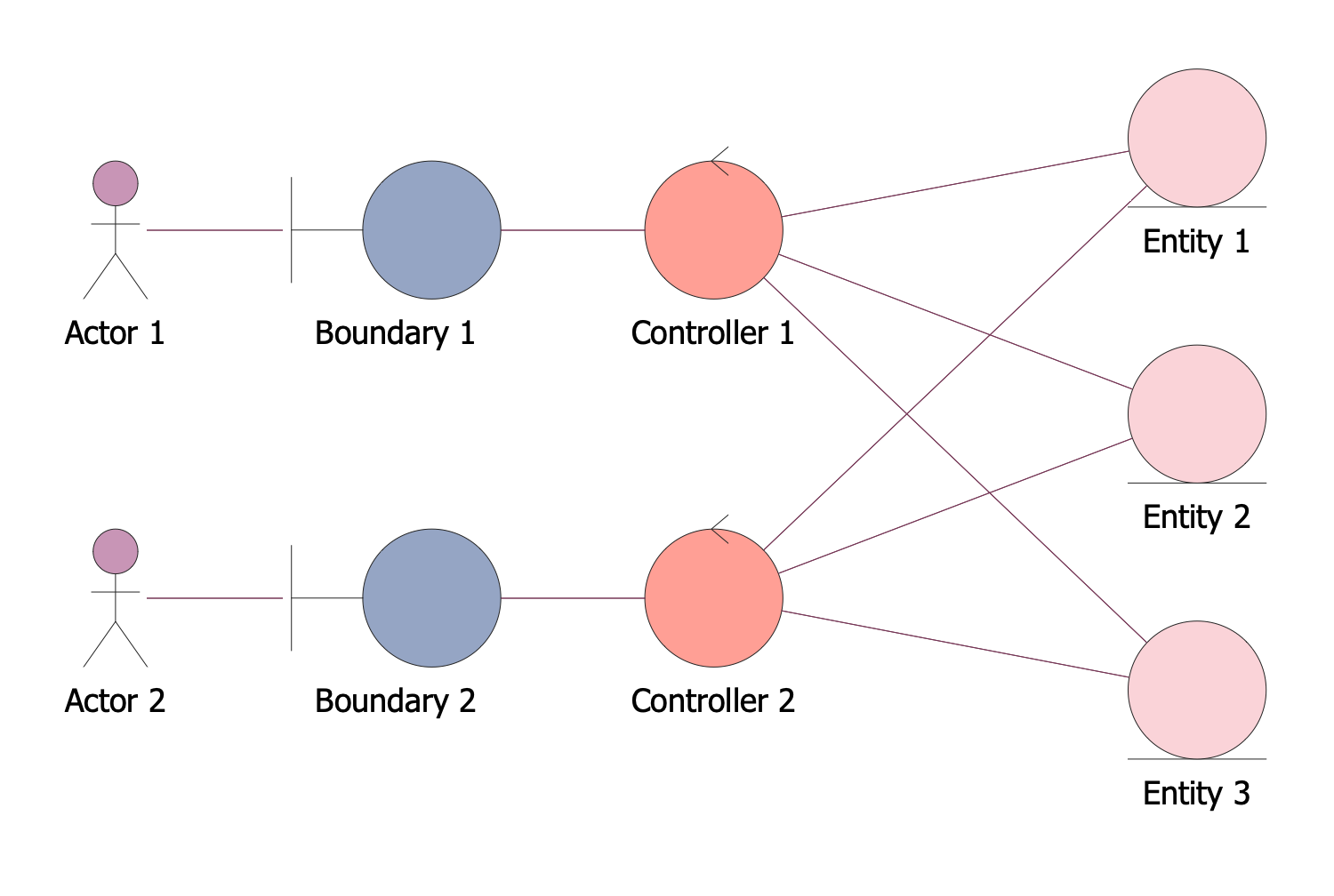
This diagram sample represents the Entity-Control-Boundary Pattern constructed in ConceptDraw DIAGRAM software using the special symbols from the common UML set of symbols. You can see the actors, boundaries, controllers, and entities connected with each other by the lines. The last three are presented in the form of circles of different colors, for each group a different color is selected; the actor looks like a man. The entities with which the system interacts in the course of its work are called actors, and each actor expects that the system will behave in a strictly defined and predictable way. The boundary is a class that is accessible from the outside, the controller is responsible for performing various operations, and the entity may contain validation or business logic. The entity classes model the long-term information that is processed by the system, as well as the behavior associated with this information. This Entity-Control-Boundary Pattern is effective when creating business-oriented components.
Example 3: Generalization in Class Diagram
This diagram was created in ConceptDraw DIAGRAM using the combination of libraries from the Class Hierarchy Tree solution. An experienced user spent 5 minutes creating this sample.
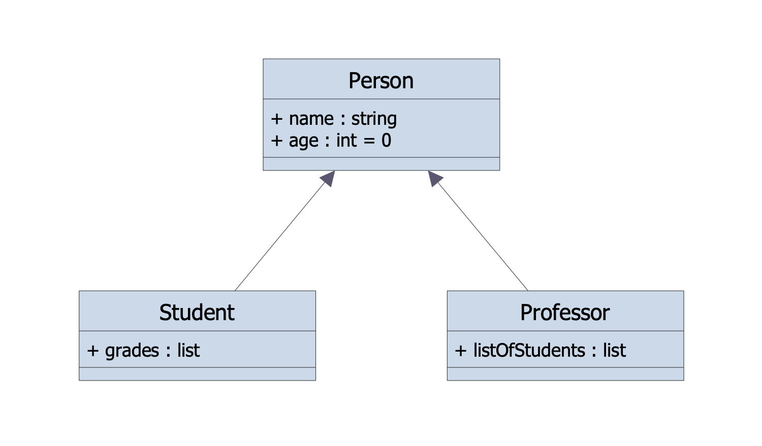
This sample illustrates the generalization in the Class Diagram. The generalization is a process of combining the common characteristics from two or more classes into one generalized superclass. These may be common attributes, methods, or associations. The generalization specifies that one of two related classes is a specialized form of the other, which is called a generalization of the first one. The superclass is considered a generalization of the subclass and is also known as the parent, base class, or base type. The subclass is also named the child, subtype, inheriting class, inheriting type, derived class, or derived type. The generalization is also known as inheritance or "is" a relationship. In this diagram, you can observe a generalization of two subclasses Student and Professor from one superclass Person. The generalization is shown by arrows from subclasses to superclass. Generalization is usually a term used only for Class Diagrams and Use Case Diagrams.
Example 4: Inheritance Hierarchy of Scala Classes
This diagram was created in ConceptDraw DIAGRAM using the combination of libraries from the Class Hierarchy Tree solution. An experienced user spent 10 minutes creating this sample.
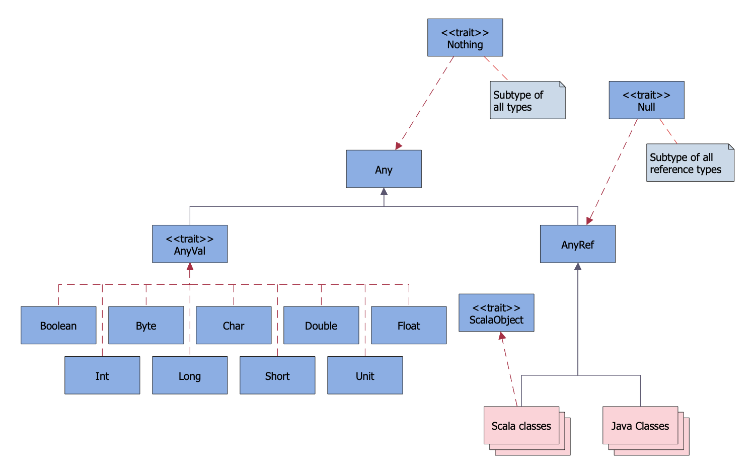
This sample demonstrates the diagram of the inheritance hierarchy of Scala classes. Scala is a statically typed, object oriented programming language that allows simple and quick creating the component software. Scala combines the functional and object oriented programming concepts, and is primarily oriented on the easy integration with applications running on the modern virtual machines such as Java (JVM). The main Scala compiler generates Java class files that can be executed under JVM. This diagram shows that classes corresponding to the primitive types in Java, such as Boolean, Byte, Char, Double, Float, Int, Long, Short, as well as Unit type extend the AnyVal class. All other classes are subclasses of the AnyRef class, which is synonymous of the Object class from the Java virtual machine or .NET. The diagram shows that all Java classes and Scala classes are subclasses of the AnyRef class. Both AnyVal and AnyRef classes in their turn extend the Any class that is the root of the hierarchy.
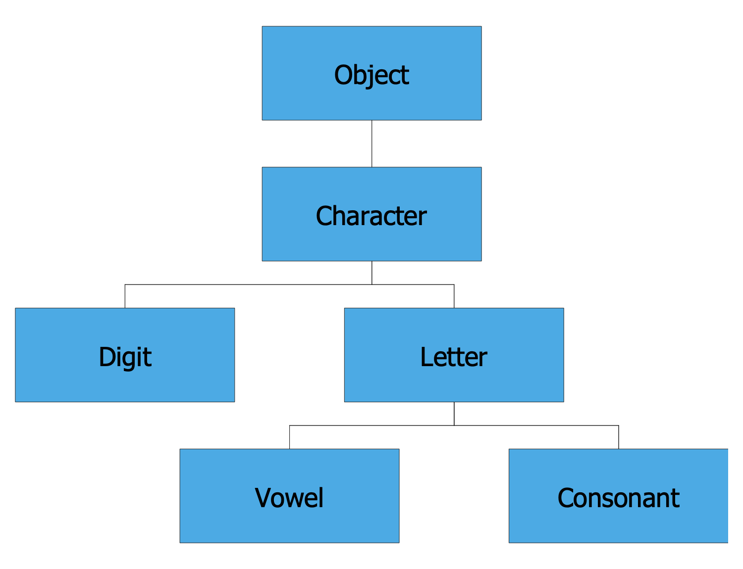
Example 5: Inheritance Tree Mindmap
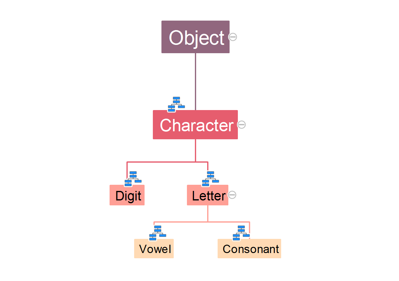
This Mind Map illustrates the inheritance tree or the class hierarchy, which is typically formed by the classes. At this, the hierarchy can be as deep as needed. As for the hierarchy of classes in Java, there is one root class — the Object class that is a superclass for all other classes in the hierarchy. The methods are inherited automatically by the classes down through the levels in the hierarchy. All methods defined in the root class are inherited by all levels placed below. This Mind Map illustrates the multiple layers of inheritance, the Object class is represented at the top. The Character class is a subclass of the Object class, so the Object is the superclass or the parent class, and the Character class is its child or derived class. The Character class has on its turn the subclasses Digit and Letter that extend it, and the Letter class also has two subclasses — Vowel and Consonant.
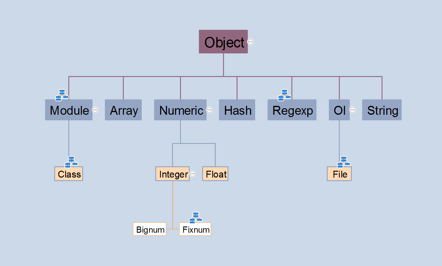
Example 6: Ruby Class Hierarchy Mindmap
This Mind Map describes the Ruby class hierarchy. Ruby is one of the youngest programming languages; it was developed by Yukihiro Matsumoto in Japan in 1995. It is a dynamic, object-oriented, high-level open source programming language with a focus on simplicity and productivity. The Ruby language was developed on the basis of well-known programming languages, combining their most convenient functions, it is closest to the Perl and Eiffel languages by its syntax features and to the Smalltalk by the object oriented approach, as well as has features from Python, Lisp, Dylan, and CLU. The list of its features includes exception handling, iterators, closures, garbage collection, threads, and many others. The language has multithreading, realized independently from the operating system. All data in the Ruby language are the objects, each function is a method. All classes are derived from the Object class, so any object can use the methods defined in it.
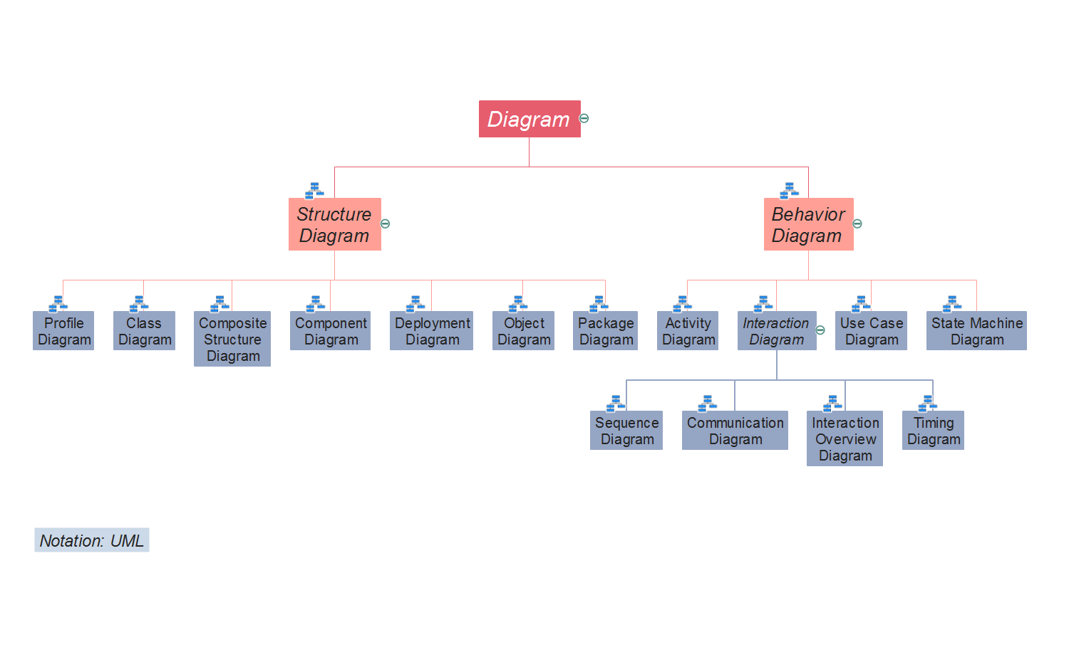
Example 7: UML 2.2 Diagrams Hierarchy Mindmap
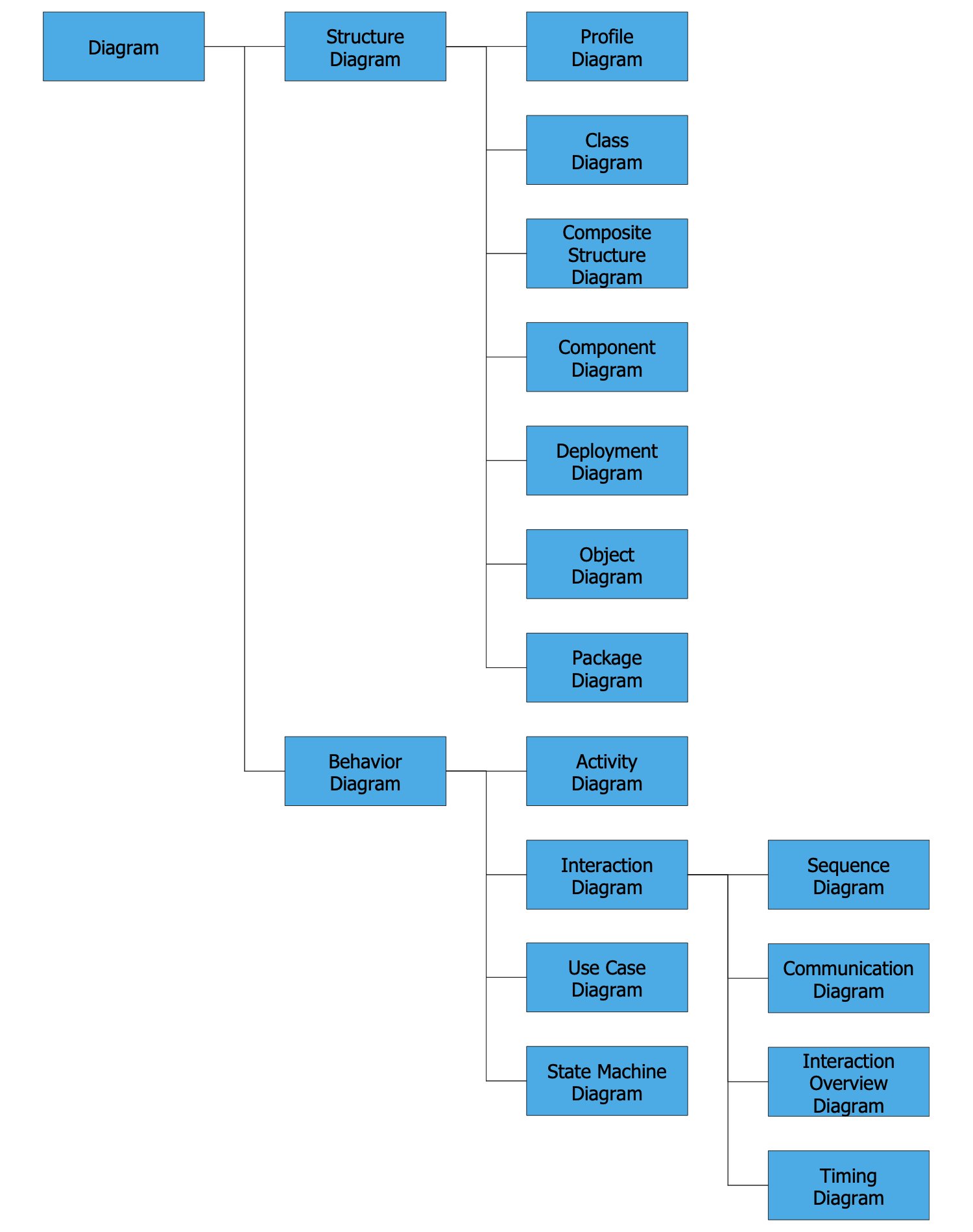
This Mind Map illustrates the hierarchy of UML 2.2 diagrams. The UML diagram is a graphical representation of the model of a system, which can be as now designed, or already implemented and existed. There are represented two major groups of UML diagrams: structure diagrams and behavior diagrams. The structure diagrams depict the static structure of the system and its parts on the different implementation and abstraction levels, how the parts are related and interact with each other. The behavior diagrams display the dynamic behavior of the system's objects, as well as the system's changes over time. Among the structure diagrams there are classified: Profile Diagram, Class Diagram, Composite Structure Diagram, Component Diagram, Deployment Diagram, Object Diagram, and Package Diagram. The behavior diagrams are represented by Activity Diagram, Use Case Diagram, State Machine Diagram, and Interaction Diagram that in its turn has several sub-types: Sequence Diagram, Communication Diagram, Interaction Overview Diagram, and Timing Diagram.
Example 8: Inheritance Tree
This sample was autogenerated to ConceptDraw DIAGRAM from the Inheritance Tree Mind Map made in ConceptDraw MINDMAP and shows the inheritance tree or in other words the class hierarchy. It is a strict tree formed from the classes that are inherited from each other from the top down. This hierarchy contains three levels, but as needed, the ConceptDraw DIAGRAM software lets one construct the hierarchy of any depth. You can observe one root class Object at the top of this hierarchy. It is a superclass or parent class because the Character class represented on the first level is its subclass or child class. The Character class is also parent class for the subclasses or child classes Digit and Letter represented on the second level. And, finally, on the third level, you can see the subclasses of the Letter class — the Vowel and Consonant classes. All methods are inherited by the classes from their parents from the top down through the hierarchy.
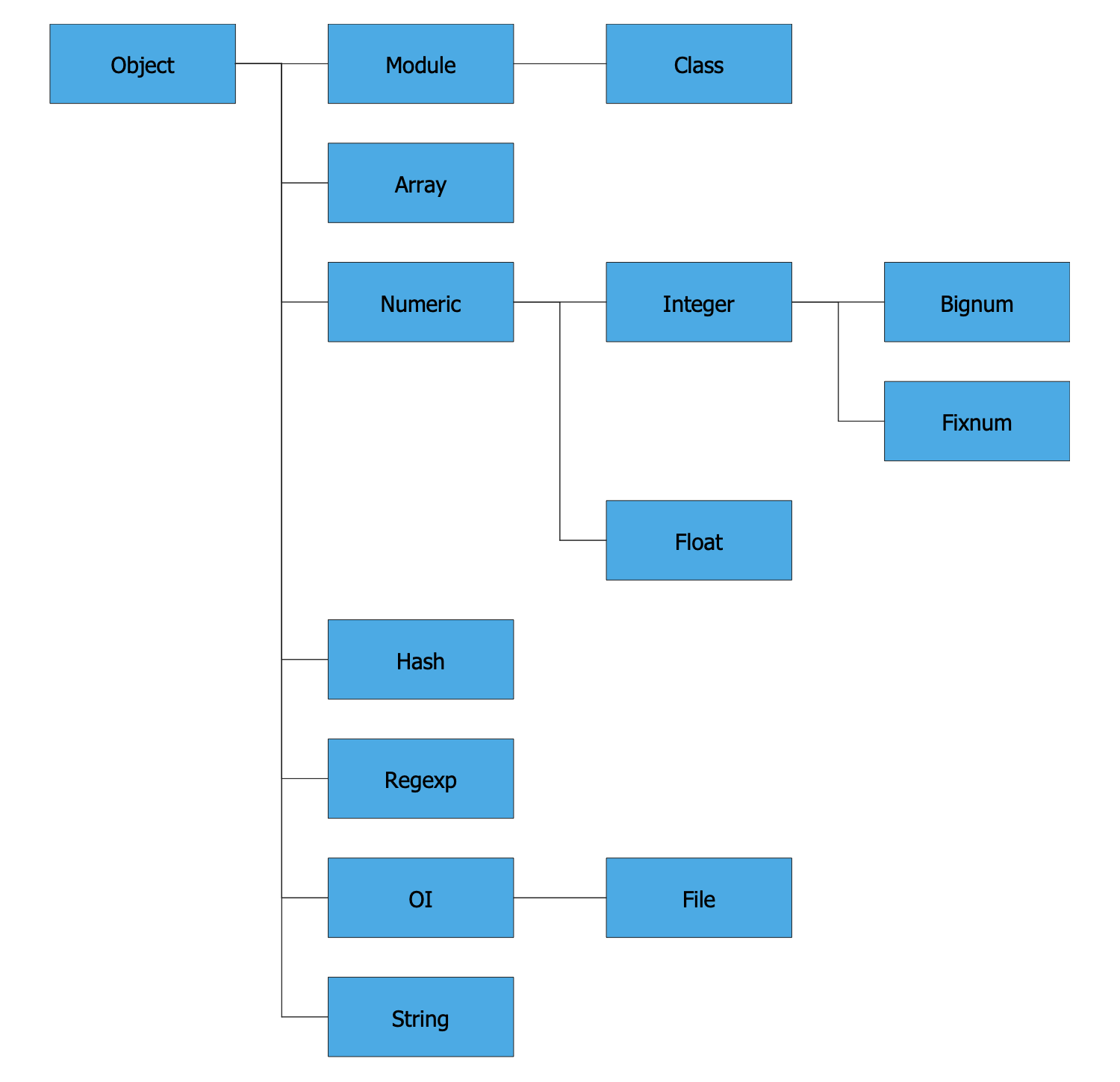
Example 9: Ruby Class Hierarchy
This sample was automatically generated from the Mind Map created in ConceptDraw MINDMAP and opened in ConceptDraw DIAGRAM. It is a Class Hierarchy Tree made for the Ruby — the object-oriented and high-level open-source programming language. Ruby is a dynamic and carefully balanced language developed by Japan programmer Yukihiro Matsumoto. Being based on such well-known programming languages as Perl, Python, Eiffel, Lisp, Dylan, CLU, it combines their best properties, features, and functionalities. The Object class is a root class in the Ruby language and all other classes are derived from it. That's why Object is placed on the top of the hierarchy and its child classes are Module, Array, Numeric, Hash, Regexp, Ol, and String. The Numeric is a base class for all numbers — Integer and Float, the Integer in its turn includes Bignum and Fixnum. The Class and File are the derivatives for Module and Ol correspondingly. The similar hierarchy can be made for any programming language — Python class hierarchy, Perl class hierarchy, Java class hierarchy, etc.
Example 10: UML 2.2 Diagrams Hierarchy
Being initially made as a Hierarchy Mind Map in ConceptDraw MINDMAP, this diagram was autogenerated and opened in ConceptDraw DIAGRAM depicting the hierarchy of UML 2.2 diagrams. The UML is a unified graphical modeling language used for describing, visualizing, designing and documenting the object-oriented systems. The UML impresses by its diversity of diagrams' kinds, you can observe in this diagram them all. Two large main groups are represented on the first level in the hierarchy: Structure diagrams and Behavior diagrams. When the first group describes the system's static structure and is represented by the Class Diagram, Composite Structure Diagram, Object Diagram, Profile Diagram, Component Diagram, Deployment Diagram, and Package Diagram, the second group includes the Use Case Diagram, Activity Diagram, Interaction Diagram, and State Machine Diagram, which depict the dynamic behavior of the system's objects. The group of Interaction Diagrams also counts several subtypes, such as Interaction Overview Diagram, Sequence Diagram, Communication Diagram, and Timing Diagram.
Inside
What I Need to Get Started
Both ConceptDraw DIAGRAM diagramming and drawing software and the Class Hierarchy Tree solution can help creating the software engineering diagrams you need. The Class Hierarchy Tree solution can be found in the Software Development area of ConceptDraw STORE application that can be downloaded from this site. Make sure that both ConceptDraw DIAGRAM and ConceptDraw STORE applications are installed on your computer before you get started.
How to install
After ConceptDraw STORE and ConceptDraw DIAGRAM are downloaded and installed, you can install the Class Hierarchy Tree solution from the ConceptDraw STORE.
Start Using
To make sure that you are doing it all right, use the pre-designed symbols from the stencil libraries from the solution to make your drawings look smart and professional. Also, the pre-made examples from this solution can be used as drafts so your own drawings can be based on them. Using the samples, you can always change their structures, colors and data.
