 Mechanical Engineering
This solution extends ConceptDraw PRO v.9 mechanical drawing software (or later) with samples of mechanical drawing symbols, templates and libraries of design elements, for help when drafting mechanical engineering drawings, or parts, assembly, pneumatic,
 ConceptDraw Solution Park
ConceptDraw Solution Park collects graphic extensions, examples and learning materials
HelpDesk
How to Create a Mechanical Diagram
Mechanical Engineering drawing is a type of technical drawing that helps analyze complex engineering systems. Mechanical Engineering diagrams are often a set of detailed drawings used for engineering or construction projects. Making Mechanical Engineering diagram involves many different elements that can be managed using ConceptDraw PRO. You can design elements for drawing parts, assembly, pneumatic, and hydraulic systems for mechanical engineering. With ConceptDraw PRO you can easily create and communicate the Mechanical Engineering diagram of any complexity."Directional control valves are one of the most fundamental parts in hydraulic machinery as well and pneumatic machinery. They allow fluid flow into different paths from one or more sources. They usually consist of a spool inside a cylinder which is mechanically or electrically controlled. The movement of the spool restricts or permits the flow, thus it controls the fluid flow. ...
While working with layouts of hydraulic machinery it is cumbersome to draw actual picture of every valve and other components.instead of pictures symbols are used for variety of components in the hydraulic system to highlight the functional aspects. symbol for directional control valve is made of number of square boxes adjacent to each other depending on the number of positions.connections to the valve are shown on these squares by capital letters.usually they are named only in their normal position and not repeated in other positions.actuation system of the valve is also designated in its symbol." [Directional control valve. Wikipedia]
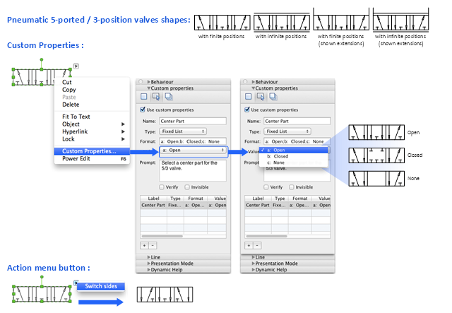
The Mac template "Pneumatic 5-ported 3-position valve" for the ConceptDraw PRO diagramming and vector drawing software is included in the Mechanical Engineering solution from the Engineering area of ConceptDraw Solution Park.
www.conceptdraw.com/ solution-park/ engineering-mechanical
 Picture Graphs
Typically, a Picture Graph has very broad usage. They many times used successfully in marketing, management, and manufacturing. The Picture Graphs Solution extends the capabilities of ConceptDraw PRO v10 with templates, samples, and a library of professionally developed vector stencils for designing Picture Graphs.
- Mechanical Drawing Symbols | Mechanical Engineering | Pneumatic ...
- Mechanical Engineering | ConceptDraw Solution Park | Total Quality ...
- Mechanical Engineering | Piping and Instrumentation Diagram ...
- Mechanical Engineering | Engineering | Technical Drawing Software ...
- How To Draw Building Plans | Vehicular Networking | Mechanical ...
- ConceptDraw Solution Park | Mechanical Engineering | Physics ...
- Mechanical Engineering | Technical drawing - Machine parts ...
- Mechanical Drawing Symbols | Mechanical Engineering | CAD ...
- Best Symbol To Represent Mechanical Engineering
- Production Chart Symbol In Mechanical Engg
- What To Mechanical Symbols Represent
- Mechanical Engineering | Making Mechanical Diagram ...
- Mechanical Drawing Symbols | Mechanical Engineering | Elements ...
- Mechanical Drawing Symbols | Mechanical Engineering | Technical ...
- Mechanical Engineering | Mechanical Drawing Symbols | Technical ...
- Mechanical Engineering | Design elements - Power sources ...
- Mechanical Drawing Symbols | Mechanical Drawing Software ...
- Mechanical Engineering Symbols Chart
- Best Vector Drawing Application for Mac OS X | Offensive Play ...
- Making Mechanical Diagram | How to Create a Mechanical Diagram ...

