 Fishbone Diagrams
The Fishbone Diagrams solution extends ConceptDraw DIAGRAM software with the ability to easily draw the Fishbone Diagrams (Ishikawa Diagrams) to clearly see the cause and effect analysis and also problem solving. The vector graphic diagrams produced using this solution can be used in whitepapers, presentations, datasheets, posters, and published technical material.
Organizational Charts with ConceptDraw DIAGRAM
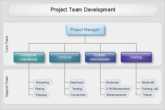
Organizational chart or Orgchart is a diagram that depicts the structure of an organization using the terms of work responsibility and rank position. It is a useful and convenient format to visually illustrate the relationships within an organization, which is moreover applicable for organization of any size. Typically, an Organizational chart is constructed from the rectangular object blocks, which represent a job title, a person's name and relationships associated with them. You looks for the powerful Orgchart software? ConceptDraw DIAGRAM software is exactly what you've been searching long. Extended with Organizational Charts Solution, ConceptDraw DIAGRAM offers great-looking examples and samples of Orgcharts, built-in templates and various types of predesigned vector block objects and connectors for creation all kinds of Organizational Charts - from simple to complex multi-page. When designing the chart for large organization with complex branched structure, may be convenient to divide it into few smaller charts.Data Flow Diagram Process
Data Flow Diagram (DFD) is a hierarchy of functional processes, connected by data flows. The purpose of this presentation is to show how each process converts its inputs into outputs and to identify relationships between these processes. DFD is convenient way of modeling and construction the information processes, it step-by-step illustrates the flow of information in a process. For construction a DFD traditionally are used two different notations, which appropriate to the methods of Yourdon-Coad and Gane-Sarson. These notations slightly different from each other by graphical representation of symbols for processes, data stores, data flow, external entities. When designing a DFD it is required to decompose the system into the components (sub-systems), for explaining a complex system you may need represent numerous levels. The Data Flow Diagrams solution from ConceptDraw Solution Park contains numerous predesigned DFD symbols for both notations, which help easy and effectively design professional-looking Data Flow Diagrams (DFDs) and DFD Process Diagrams.- Workflow Chart
- Data Flow Diagram Model
- Data Flow Diagram Model | DFD - Model of small traditional ...
- Flowchart Marketing Process. Flowchart Examples | Marketing and ...
- Data Flow Diagram
- Sales Process Flowchart . Flowchart Examples | Sales Process Steps ...
- Example of DFD for Online Store (Data Flow Diagram ) DFD ...
- Process Flowchart | Data Flow Diagrams | Basic Flowchart Symbols ...
- Example of DFD for Online Store (Data Flow Diagram ) DFD ...
- Data Flow Diagram Order
- Detailed Data Flow Diagram
- Data Flow Diagram
- Data Flow Diagram Model | Example of DFD for Online Store (Data ...
- Data Flow Diagram Model | Example of DFD for Online Store (Data ...
- Data Flow Diagrams
- Data flow diagram (DFD) - Payment for goods using UPS code ...
- Data Flow Diagram (DFD) | Data Flow Diagram Process | DFD ...
- Data Flow Diagram Software | DFD - Process of account receivable ...
- Data flow Model Diagram | DFD, Gane-Sarson notation - Template ...
- Context Diagram Template | DFD Library System | Data Flow ...

