How To use Architect Software

Create Floor Plans Easily with ConceptDraw DIAGRAM

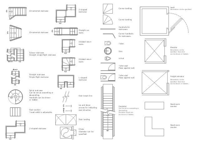
The design elements library Building core contains 80 symbols of stairs, elevators, escalators, restroom fixtures, and a safe.
Use the shapes library Building core to draw the structural diagrams, bathroom layouts, building automation, architectural drawings, and riser diagrams, as well as space plans, store and shopping mall plans, and facility planning, plant layouts using the ConceptDraw PRO diagramming and vector drawing software.
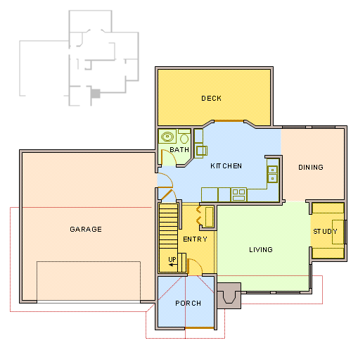
"In architecture and building engineering, a floor plan otherwise known as a Scottish plan is a drawing to scale, showing a view from above, of the relationships between rooms, spaces and other physical features at one level of a structure.
The term may be used in general to describe any drawing showing the physical layout of objects.
A floor plan could show:
Interior walls and hallways;
Restrooms;
Windows and doors;
Appliances such as stoves, refrigerators, water heater etc.;
Interior features such as fireplaces, saunas and whirlpools;
The use of all rooms shall be indicated." [Floor plan. Wikipedia]
The vector stencils library Building core is provided by the Floor Plans solution from the Building Plans area of ConceptDraw Solution Park.
Use the shapes library Building core to draw the structural diagrams, bathroom layouts, building automation, architectural drawings, and riser diagrams, as well as space plans, store and shopping mall plans, and facility planning, plant layouts using the ConceptDraw PRO diagramming and vector drawing software.
"In architecture and building engineering, a floor plan otherwise known as a Scottish plan is a drawing to scale, showing a view from above, of the relationships between rooms, spaces and other physical features at one level of a structure.
The term may be used in general to describe any drawing showing the physical layout of objects.
A floor plan could show:
Interior walls and hallways;
Restrooms;
Windows and doors;
Appliances such as stoves, refrigerators, water heater etc.;
Interior features such as fireplaces, saunas and whirlpools;
The use of all rooms shall be indicated." [Floor plan. Wikipedia]
The vector stencils library Building core is provided by the Floor Plans solution from the Building Plans area of ConceptDraw Solution Park.
ConceptDraw DIAGRAM : Able to Leap Tall Buildings in a Single Bound
Network Glossary Definition


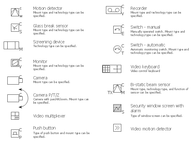
The vector stencils library Video surveillance contains 15 symbols of electronic closed-circuit television (CCTV) equipment, digital video cameras and recording devices and covert video equipment.
"Closed-circuit television (CCTV) is the use of video cameras to transmit a signal to a specific place, on a limited set of monitors. It differs from broadcast television in that the signal is not openly transmitted, though it may employ point to point (P2P), point to multipoint, or mesh wireless links. Though almost all video cameras fit this definition, the term is most often applied to those used for surveillance in areas that may need monitoring such as banks, casinos, airports, military installations, and convenience stores.
In industrial plants, CCTV equipment may be used to observe parts of a process from a central control room, for example when the environment is not suitable for humans. CCTV systems may operate continuously or only as required to monitor a particular event. A more advanced form of CCTV, utilizing digital video recorders (DVRs), provides recording for possibly many years, with a variety of quality and performance options and extra features (such as motion-detection and email alerts). More recently, decentralized IP cameras, some equipped with megapixel sensors, support recording directly to network-attached storage devices, or internal flash for completely stand-alone operation. Surveillance of the public using CCTV is particularly common in many areas around the world." [Closed-circuit television. Wikipedia]
Use the design elements library Video surveillance to design the layout plans of security and access systems, and internal and external video surveillance and security control monitoring systems using the ConceptDraw PRO diagramming and vector drawing software.
The shapes library Video surveillance is included in the Security and Access Plans solution from the Building Plans area of ConceptDraw Solution Park.
Video surveillance symbols
Comparing ConceptDraw DIAGRAM to Omnigraffle

- How To use Office Layout Software | Office plan - Cubicle layout ...
- Building Drawing Software for Design Office Layout Plan | How To ...
- Building Drawing Software for Design Office Layout Plan | How To ...
- How To use Office Layout Software | How To Draw Building Plans ...
- Office - Design Elements | Building Drawing Software for Design ...
- Building Drawing Software for Design Office Layout Plan
- Building Drawing Software for Design Office Layout Plan | Interior ...
- Building Drawing Software for Design Office Layout Plan | How To ...
- Building Drawing Software for Design Office Layout Plan | How To ...
- How To use Office Layout Software | Building Drawing Software for ...
- Building Drawing Software for Design Office Layout Plan
- How To use Office Layout Software | How To Draw Building Plans ...
- Building Drawing Software for Design Office Layout Plan
- How To Draw Building Plans | Building Drawing Software for Design ...
- How To use Office Layout Software | Building Drawing Software for ...
- How To Draw Building Plans | Building Drawing Software for Design ...
- How To use Office Layout Software | How To Create Home Plan with ...
- Building Drawing Software for Design Office Layout Plan | Interior ...
- Building Drawing Software for Design Office Layout Plan | How To ...
- Building Drawing Software for Design Office Layout Plan | How To ...